I/O Connection
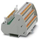
DIAP can be connected to PLCs, sensors or industrial robots via I/O connectivity. A breakout box is supplied together with the DIAP. Please pay attention when connecting the DIAP via the breakout box and follow the below instructions thoroughly to avoid damaging the DIAP and other equipment.
The I/O board is galvanically isolated from the DIAP CPU. It is possible to supply power to the I/O board directly from the power supply of the machine/line or from the power supply of the DIAP CPU.
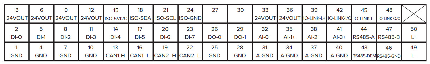
The terminals on the breakout box are placed in the following way:
Sensor power supply
Please note that 24V DC must be applied to terminal 50 (+24V interface supply) with reference to terminal 49 (GND supply) for the sensor interface to be functional.
| Terminal # | Signal |
| 3 | +24VDC for sensors |
| 6 | +24VDC for sensors |
| 9 | +24VDC for sensors |
| 12 | +24VDC for sensors |
| 33 | +24VDC for sensors |
| 36 | +24VDC for sensors |
| 50 | +24VDC supply |
| 49 | GND supply |
| 1 | GND |
| 4 | GND |
| 7 | GND |
| 10 | GND |
| 25 | GND |
| 28 | GND |
Digital inputs
It is possible to connect up to 8 digital sensors of the type PNP directly to the DIAP, with refresh rates down to a 100ms
| Terminal # | Signal |
| 2 | Digital input 0 |
| 5 | Digital input 1 |
| 8 | Digital input 2 |
| 11 | Digital input 3 |
| 14 | Digital input 4 |
| 17 | Digital input 5 |
| 20 | Digital input 6 |
| 23 | Digital input 7 |
| 26 | Digital output 0 |
| 29 | Digital output 1 |
Analog inputs
It is possible to connect up to 4 analog sensors (4-20 mA) directly to the DIAP. Both 2-wire and 3-wire sensors can be connected.
| Terminal # | Signal |
| 32 | Analog input 0 |
| 35 | Analog input 1 |
| 38 | Analog input 2 |
| 41 | Analog input 3 |
| 31 | Analog ground |
| 34 | Analog ground |
| 37 | Analog ground |
| 40 | Analog ground |
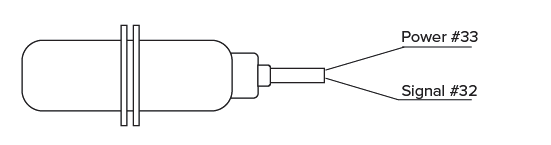
Example of connection of 2-wire analog sensor:
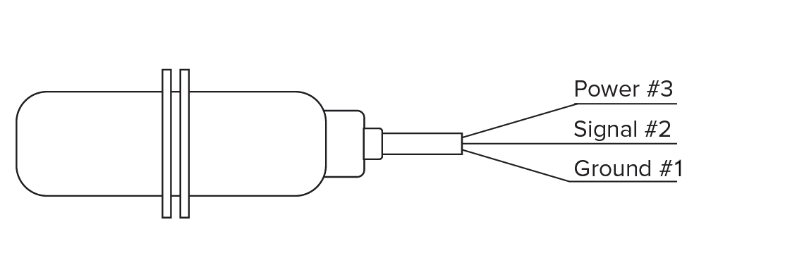
Example of connection of 3-wire digital sensor:
Connection of CAN-bus
There is two CAN-bus connections. Bus termination is performed by means of connection J9 inside the diap.
| Terminal # | Signal |
| 13 | CAN 1 HIGH |
| 16 | CAN 1 LOW |
| 19 | CAN 2 HIGH |
| 22 | CAN 2 LOW |
Connection of RS485
The isolated RS485 is connected using the following terminals, Bus termination is performed by means of connection J10 inside the diap.
| Terminal # | Signal |
| 44 | RS485-A |
| 47 | RS485-B |
| 43 | RE485-DEM |
| 46 | RE485-GND |
Connection of I2C-BUS
The I2C-BUS is for expansion in the future.
| Terminal # | Signal |
| 15 | ISO-5V12C |
| 18 | ISO-SDA |
| 21 | ISO-SCL |
| 24 | ISO-GND |
Terminals not to be used.
| Terminal # | Signal |
| 27 | NOT TO BE USED |
| 30 | NOT TO BE USED |
| 39 | NOT TO BE USED |
| 42 | NOT TO BE USED |
| 45 | NOT TO BE USED |
| 48 | NOT TO BE USED |