Introduction
This is a guide for how to configure Modbus RTU for DIAP.
The DIAP support: 9600/8-N-1 and many more combinations
- Bytesize: 8 bits
- Parity: no parity
- Stop bit: 1 stop bit
- Baud rate: 9600
Configuration
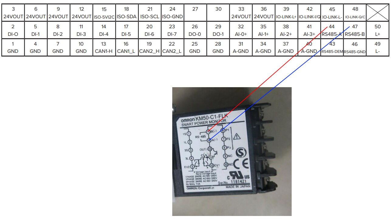
Modbus RTU is modbus via RS-485 2 wire connection.
Firstly, make sure to connect the wires correctly as the communication needs to be crossed (see example below).
Rs485-A = +
Rs485-B = -
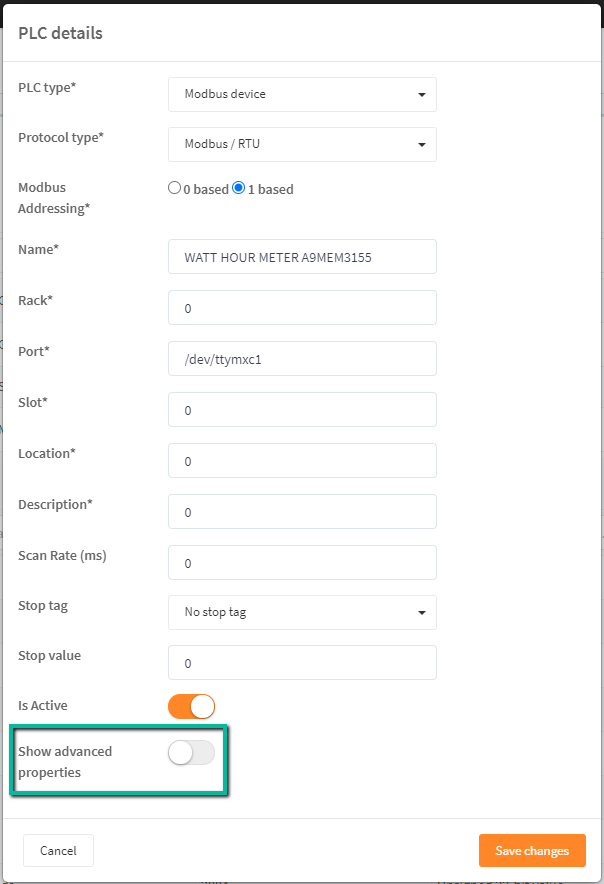
Secondly, fill in the required information for configuration of the PLC:
- In the PLC type dialog box select Modbus device
- In the Protocol type dialog box select Modbus / RTU
- Select if the system is based on 0 or 1 (if the first register is 0 or 1)
- In the Name dialog box write the Name of the device you are connecting to
- Port - always /dev/ttymxc1.
- All dialog boxes marked with 0 is not in used
- Remember to toggle the "show advanced properties" switch, marked in green box.
Please see the following example:
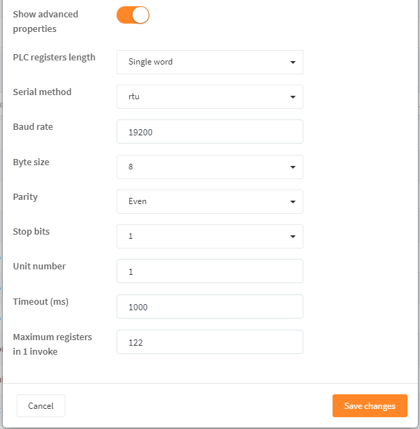
After toggling the "show advanced properties" switch the set up for communication will appear.
- In the "PLC registers length" you can choose the length of the register single word (16 bit ) or double word ( 32 bit ) the most commonly is single word.
- In "serial methode" you can choose between the two standards rtu or ascii (rtu is the most common)
- in "Baud rate" you can type the speed to use, most common as default is 9600 baud
Baud Rate 1200 bps 2400 bps 4800 bps 9600 bps 19200 bps 38400 bps 57600 bps 115200 bps - In "Byte size" you can choose the length of the Byte most commonly used is 8 bit.
- In "parity" you select from the following None,Even,Odd,Mark,space most commonly used is none
- In "Stop bit" most commonly used is 1 you can select 1,5 and 2
- In "Unit number" you write the address number / device id for the unit you want to contact (Range 1-255)
- In "Timeout (ms)" you set timeout for communication
- In "Maximum registers in 1 invoke" you can set the number of registers to be read in one call standard is 122 if for some reason you device only supports to send 10 registers at a time it can be lowered. (Range 1-122)
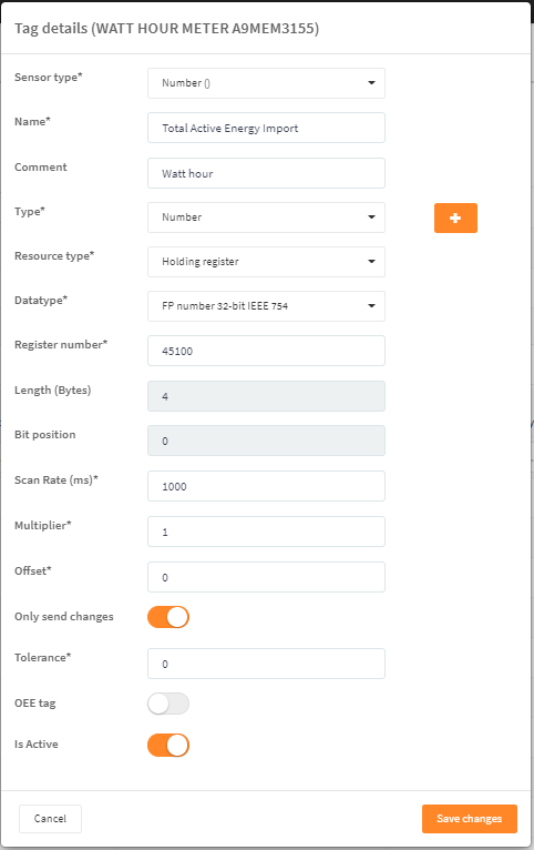
Thirdly, specify the tags.
- In "sensor type" choose what is measured
- In "Name" write the tag name
- in "comment" you can write a long tekst that gives better elaboration than name, but it can be left blank.
- In "Type" choose from the list what identifies the value is it volts, Number, Time and so on.
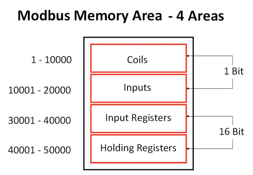
- Specify Resource type. If this is not provided by the vendor, you can use the table below to translate the direct addresses keep in mind that this is 1 based, if changed to 0 based the numbers will shift so that coils will be at 0-09999 inputs at 10000-19999 and so on.
- In "Datatype" you choose signet/unsigned ,16-32-bit or Floating point 32-bit
- In "Register number" write the register number
- In "Length (Byte) the length is shown
- In "Bit position" when not grayed out and binary tag is chosen in "data type" you can write the exact bit you want to read.
- In "Scan Rate (ms)" the speed is written can not be less than the main scan rate.
- In "Multiplier" the value written her is multiplied with the read value.
- In "Offset" a start offset can be written if 2 is entered and the value read is 10 the output will be 12
- The toggle switch "Only send changes" is if you have the same value over a period of time it will not be send, only if the value changes it will be send. Good for lowering the data amount send to azure.
- In "Tolerance" if 0 is written alle value will be send, if 2 is written the value must be 2 numbers bigger or smaller to be send again good for flickering in analog values.
- The toggle switch "OEE tag" is for revealing this tag in OEE.
- The toggle switch "Is Active" is for activating the tag, if off tag will not be read.